Ring and Pinion Pattern Chart 2026: Complete Fix Guide
How to read a ring and pinion contact pattern: Spicer's face milled and face hobbed charts, Ford's pattern-movement rules, and Yukon backlash ranges by axle.

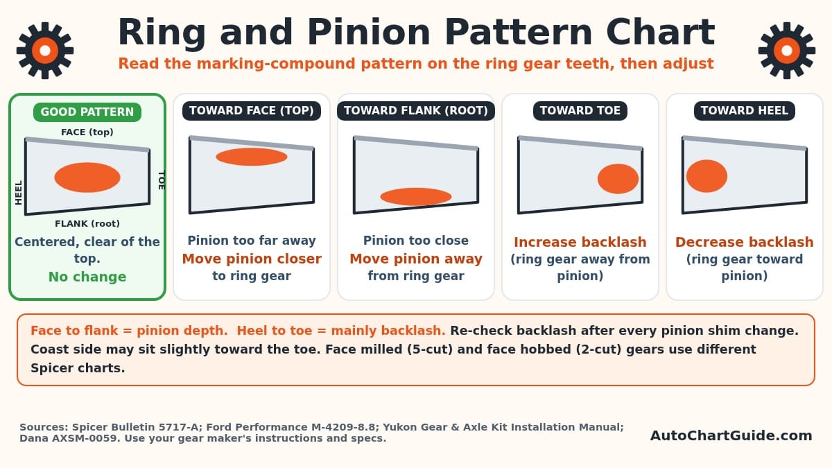
Short answer: A ring and pinion pattern chart tells you what the gear-marking-compound pattern on your ring gear teeth means and what to adjust. A good pattern is centered on the drive side, centered or slightly toward the toe on the coast side, and clear of the top of the tooth. A pattern toward the face (top) means the pinion is too far from the ring gear, so move it closer. A pattern toward the flank (root) means the pinion is too close, so move it away. A pattern crowding the toe needs more backlash; one crowding the heel needs less.
We built this chart from manufacturer documents, all read on November 3, 2026. The main tables come from Spicer Technology (Dana) Bulletin 5717-A, Ring Gear and Pinion Tooth Pattern Interpretation (dated 5/02) and Ford Performance's M-4209-8.8 ring and pinion instruction sheet. Yukon Gear & Axle's Kit Installation Manual (the PDF linked from its install manuals page, dated August 2026) and Dana's Spicer S132 Series service manual, AXSM-0059 add more detail. Short quotes are copied word for word. We have not set up a differential for this article, and we do not invent settings. Where the documents disagree, we say so.
One note before you start. Pinion bearing preload and the bolt torques for ring gear bolts and bearing caps are torque values, and this site does not republish them. Take them from your gear set's instructions or the axle's factory service manual. Our guide to finding the right torque specs for your vehicle explains where those documents live.
Ring and pinion pattern chart: what each pattern means
This is the quick-reference version. It combines Spicer's and Ford's description of the desirable pattern, Yukon's face-to-flank rule for pinion depth, and Dana's heel-to-toe rule for backlash. Read the pattern on the ring gear, not the pinion. Check both the drive side and the coast side.
| What the pattern shows | What it means | Fix | Source |
|---|---|---|---|
| Centered on the drive side, coast side centered or a little toward the toe, clear of the top of the tooth | Desirable pattern | None | Spicer Bulletin 5717-A; Ford M-4209-8.8 |
| Pattern sits toward the face (top land) of the tooth | Pinion is too far from the ring gear | Move the pinion toward the ring gear centerline | Yukon Kit Installation Manual |
| Pattern sits toward the flank (root) of the tooth | Pinion is too close to the ring gear | Move the pinion away from the ring gear centerline | Yukon Kit Installation Manual |
| Pattern runs too close to the toe (inner end) | Backlash too tight for this pattern | Move the ring gear away from the pinion to increase backlash | Dana AXSM-0059 |
| Pattern concentrated at the heel (outer end) | Backlash too loose for this pattern | Move the ring gear toward the pinion to decrease backlash | Dana AXSM-0059 |
| Hard line where the pressure is high | Not an acceptable pattern | Reset pinion depth and backlash | Ford M-4209-8.8 |
Face, flank, heel and toe refer to the ring gear tooth. Always re-measure backlash after any pinion shim change, because the two settings interact.
The chart has two axes because there are two main adjustments. Pinion depth (the pinion position shim) mainly moves the pattern up and down the tooth, between face and flank. Backlash (the ring gear position) mostly moves it along the tooth, between heel and toe. Dana's S132 manual says ring gear position "moves the contact pattern along the face width of the gear tooth." Spicer's single drive axle manual (AXSM-8941) says the pinion and backlash adjustments "are interrelated" and must be "considered together even though the pattern is altered by two distinct operations."
Spicer Bulletin 5717-A and Ford's 8.8 sheet both carry the same warning about this: "When making changes, note that two variables are involved." If backlash is correct and you change the pinion shim, you may have to reset backlash before the next pattern check will tell you anything.
Ring gear tooth names: heel, toe, face, flank, drive and coast
Every pattern chart uses the same six words. If you mix them up, every fix comes out backwards, so it is worth getting them straight first.
| Term | Where it is | Source wording |
|---|---|---|
| Toe | The inner end of the tooth, nearest the center of the ring gear | "the portion of the tooth surface at the end towards the center" (Spicer 5717-A) |
| Heel | The outer end of the tooth, at the ring gear's outside diameter | "the portion of the tooth surface at the outer-end" (Spicer 5717-A) |
| Face / top land | The top of the tooth | "The TOP LAND of a gear tooth is the surface of the top of the tooth" (Spicer 5717-A); Yukon labels it "Face (Top Land)" |
| Flank / root | The bottom of the tooth, in the valley between teeth | Yukon labels it "Flank (Root)" |
| Drive side | The convex side of the ring gear tooth | "Drive pattern (convex side of gear)" (Ford M-4209-8.8) |
| Coast side | The concave side of the ring gear tooth | "Coast pattern (concave side of gear)" (Ford M-4209-8.8) |
The drive side is the one loaded when the engine pulls the vehicle forward. The coast side is loaded when you lift off the throttle and the vehicle drives the engine. A gear set can show a good drive pattern and a poor coast pattern at the same time, which is why every chart below has two columns.
Face milled vs. face hobbed gears: pick the right chart
Spicer's bulletin gives two separate pattern charts because gear sets are cut by two different methods. Its instruction is blunt: "You must first determine the type of gear that you have in order to know which gear pattern chart to use." The test is tooth depth. "If the gear was manufactured using the FACE HOBBING method, both 'A' and 'B' will be of equal depth. If the gear was manufactured using the FACE MILLING method, 'A' will be larger than 'B'." Revolution Gear describes the same test in heel and toe terms, below.
Gear makers often use the shop names instead. Revolution Gear & Axle's explainer on 2-cut vs. 5-cut gears lists "Face milling, or five-cut" and "Face hobbing, or two-cut." It says a face milled ring gear's heel "is taller than the Toe," while a face hobbed ring gear "has constant depth from heel to toe." It also notes that two-cut gears show a natural "bias," so the pattern "shows up slanted," and that OE manufacturers mostly use the two-cut method. This matters for backlash too, because Yukon's spec table lists separate "5 cut" and "2 cut" backlash columns.
Face milled (5-cut) pattern chart
| Drive side (convex) | Coast side (concave) | Action Spicer gives |
|---|---|---|
| Centered on the tooth, clearance to the top | Centered, may be slightly toward the toe, clearance to the top | None (desirable pattern) |
| Top heel contact | Top toe contact | Backlash correct. Thicker pinion position shim required. |
| Root toe contact | Root heel contact | Backlash correct. Thinner pinion position shim required. |
| Top heel contact | Top heel contact | Pinion position shim correct. Decrease backlash. |
| Root toe contact | Root toe contact | Pinion position shim correct. Increase backlash. |
Source: Spicer Technology, Inc. Bulletin 5717-A (5/02), "Pattern Interpretation (Ring Gear), Face Milling," page 2 of 3. Wording copied from the bulletin.
Face hobbed (2-cut) pattern chart
| Drive side (convex) | Coast side (concave) | Action Spicer gives |
|---|---|---|
| Centered on the tooth, clearance to the top | Centered, may be slightly toward the toe, clearance to the top | None (desirable pattern) |
| Top toe contact | Top heel contact | Backlash correct. Thicker pinion position shim required. |
| Root heel contact | Root toe contact | Backlash correct. Thinner pinion position shim required. |
| Top heel contact | Top toe contact | Pinion position shim correct. Decrease backlash. |
| Root toe contact | Root heel contact | Pinion position shim correct. Increase backlash. |
Source: Spicer Technology, Inc. Bulletin 5717-A (5/02), "Pattern Interpretation (Ring Gear), Face Hobbing," page 3 of 3. Wording copied from the bulletin.
Compare the two tables row by row. On the drive side, both methods give the same answers for backlash: top heel contact means decrease backlash, and root toe contact means increase it. The differences show up in the pinion-shim rows and on the coast side. On a face milled gear, "top heel" drive contact with "top toe" coast contact calls for a thicker pinion shim. On a face hobbed gear, the same thicker-shim call comes from "top toe" drive and "top heel" coast. Using the wrong table can point you toward the wrong fix.
Not every chart agrees on the face hobbed backlash rows. Weber State University's transmission lab handout, Ring Gear Contact Pattern Interpretation of Face Hobbed Gear Teeth (2011), shows "Heel-Heel" (drive and coast both toward the heel) as the decrease-backlash case and "Toe-Toe" as the increase-backlash case. Spicer's bulletin shows the coast side moving the other way. The pinion-depth rows match: Weber's toe-heel pattern means "Move the pinion gear closer," and its heel-toe pattern means "Move the pinion gear away." When charts disagree, follow the instructions that came with your gear set. Spicer's heavy-duty manual also lists a service line (1-800-826-HELP) for cases where an acceptable pattern cannot be reached within backlash limits.
How the pattern moves when you change each setting
The interpretation tables tell you where to go. This table tells you what each change does, which helps when a pattern sits between two textbook cases. It is Ford's Step 4 summary from the 8.8 sheet.
| Change you make | Drive pattern (convex side) moves | Coast pattern (concave side) moves |
|---|---|---|
| Decrease backlash (ring gear closer to pinion) | Slightly lower and toward the toe | Lower and toward the toe |
| Increase backlash (ring gear away from pinion) | Slightly higher and toward the heel | Higher and toward the heel |
| Thicker pinion position shim, backlash constant (pinion closer to ring gear) | Deeper on the tooth (flank contact) and slightly toward the toe | Deeper on the tooth and toward the heel |
| Thinner pinion position shim, backlash constant (pinion farther from ring gear) | Toward the top of the tooth (face contact) and toward the heel | Toward the top of the tooth and slightly toward the toe |
Source: Ford Performance M-4209-8.8 instruction sheet, Tooth Contact Patterns, Step 4. Yukon's manual gives the same directions in terms of moving the pinion closer or farther away.
Two practical points follow from this table. First, a pinion shim change moves the drive and coast patterns in opposite directions along the tooth: a thicker shim sends drive toward the toe and coast toward the heel. That is why a "toe on one side, heel on the other" pattern is a pinion-depth problem, not a backlash problem. Second, a backlash change moves both sides the same way, toward the toe when you tighten and toward the heel when you loosen. If both sides crowd the same end, look at backlash first.
"Thicker" and "thinner" only work as directions when you know where the shim sits. In Ford's 8.8 axle, the drive pinion bearing adjustment shim (0.010 to 0.038 inch, per Ford) sits "between differential pinion bearing and pinion head," so a thicker shim pushes the pinion toward the ring gear. Yukon warns that "not all housings are shimmed in the same location," and Ford's M-4209-G430M instructions add the line "Reverse this procedure for 8" and 9" Ford." Yukon's wording, moving the pinion toward or away from the ring gear centerline, works on any axle, so think in those terms. If you are not sure how your housing is shimmed, an exploded parts diagram for the axle shows where the shims sit.
How to make a readable contact pattern
A pattern chart only helps if the pattern is clean. The manufacturers describe slightly different methods, and all of them work:
- Use real gear marking compound. Yukon says anything else, "such as blue machinist dye," will not give a clear indication of tooth contact. It suggests thinning the compound with a little oil if needed to make "a smooth, but not runny, paste."
- Paint enough teeth. Yukon coats "three or four ring-gear teeth in at least two places." Dana's S132 manual paints "six ring gear teeth 180° apart." Ford paints the teeth "to both the drive and coast side."
- Load the gears while you roll them. Ford's 8.8 sheet says to "rotate ring gear one complete revolution in both directions" and to "apply load with a large screwdriver or similar tool between the carrier casting and differential case flange." Yukon rotates the ring gear "four or five times around the pinion gear in both directions," turning the ring gear rather than the pinion, and adds drag by wrapping a shop towel around the yoke.
- Read every painted area. Weber State's handout says to "observe all gear teeth for proper contact pattern and a uniform pattern from tooth to tooth." If the pattern changes around the gear, check how the ring gear is mounted: Ford's G430M sheet says tooth depth variations "can result from a ring gear that is 'cocked' on its mounting surface," and Ford's 8.8 sheet sets maximum differential case runout at .003 inch.
- Photograph both sides before you wipe the compound off. That gives you a record to compare after each change, and for a used set it records the wear pattern you will need to reproduce.
Patterns made by hand are light-load patterns. Dana says the length of a new-gear pattern "in an unloaded condition is approximately one-half (1/2) to two-thirds (2/3) of the ring gear tooth in most models and ratios." Dana adds that the pattern "could vary in length and should cover half (1/2) of the tooth or more (face width)," evenly centered between top land and root and "up off the tooth toe."
Order of adjustments
Yukon lists the setup adjustments in this order: "1. Pinion Depth 2. Pinion-Bearing Preload 3. Backlash 4. Carrier-Bearing Preload." For a baseline, it says to reassemble with "the shim combinations that were used in the differential during the previous assembly." Ford's 8.8 sheet says the same about Ford gears: reusing the original pinion shim thickness on a new Ford Racing gear "most times will allow you to achieve correct tooth contact pattern with only minor adjustments."
In practice, Yukon's procedure does a trial pinion assembly, sets an initial backlash ("This initial backlash setting sets the basis for all future adjustments"), and then reads the pattern to judge pinion depth. Spicer's AXSM-8941 manual says "first adjust the pinion, then the backlash. Continue this sequence until the pattern is satisfactory." Both reach the same place: pinion depth decides the face-to-flank position, and backlash is reset inside its spec after every pinion change. Do the final pinion bearing preload with a new crush sleeve or the correct shim pack once depth is right. Yukon says final assembly "always requires a new crush sleeve."
Some gear sets come with a target. Ford says each Ford Racing ring and pinion "is pre-run and marked on the pinion face with its proper depth setting called the 'Checking Distance'," measured from the pinion face to the axle centerline with a setting tool, and to "stay +/-.002 of the pinion dimension." Ford also notes that its gears are lapped in sets and "should never be mixed with another ring gear or pinion," so check that the serial numbers on the ring and pinion match. Quick change rears pair the ring and pinion with a set of swappable spur gears; our Winters quick change gear chart lists the final drive ratio each gear set gives. If you are working on a GM vehicle and want to confirm what it was built with before ordering parts, our guide to the GM RPO sticker explains where to find the factory option codes and how to read them.
Backlash specs and how much to move the shims
Backlash is the free movement of the ring gear while the pinion is held still. Yukon measures it with a dial indicator mounted "on the same plane as the ring gear," with the tip touching a tooth "at the outermost diameter of the ring gear 90 degrees to the tooth face." Ford's 8.8 sheet calls for checking it at four locations, with no more than .004 inch variation.
The right number depends on the gear set and the axle. Ford Performance says its ring gears and pinions "are developed to be run at .008" to .012" backlash for street gear sets." Dana's S132 manual gives .006 to .018 inch for new gearing on that heavy-duty axle and says to reset used gearing to the backlash recorded before disassembly. Yukon's spec table lists ranges by axle and by gear type:
| Axle (as Yukon names it) | Backlash, "5 cut" column (inch) | Backlash, "2 cut" column (inch) |
|---|---|---|
| Dana 30 (D30) | .006-.011 | not listed |
| Dana 44 (D44) | .006-.011 | .004-.007 |
| Dana 60, 61 & 70U | .006-.011 | .005-.008 |
| Ford 7.5" | .011-.016 | not listed |
| Ford 8.8" | .006-.011 | .011-.016 |
| Ford 9.0" OEM R&P | .010-.016 | not listed |
| GM 8.5" & 8.6" | .006-.011 | .003-.006 |
| GM 9.5" (AAM straight axle) | .006-.011 | .004-.008 |
| AAM 11.5" (2018 & older) | .006-.011 | .005-.007 |
| Chrysler 9.25" rear | .006-.011 | .005-.009 |
| Toyota 8" front or rear | .006-.011 | not listed |
Source: Yukon Gear & Axle Kit Installation Manual, "Set Up Specifications" table (B/L columns, listed in thousandths of an inch), PDF linked from Yukon's install manuals page, read November 3, 2026. "Not listed" means the 2 cut cell is blank for that axle. Yukon's table also lists pinion bearing preload and bolt torque; we do not reproduce torque values.
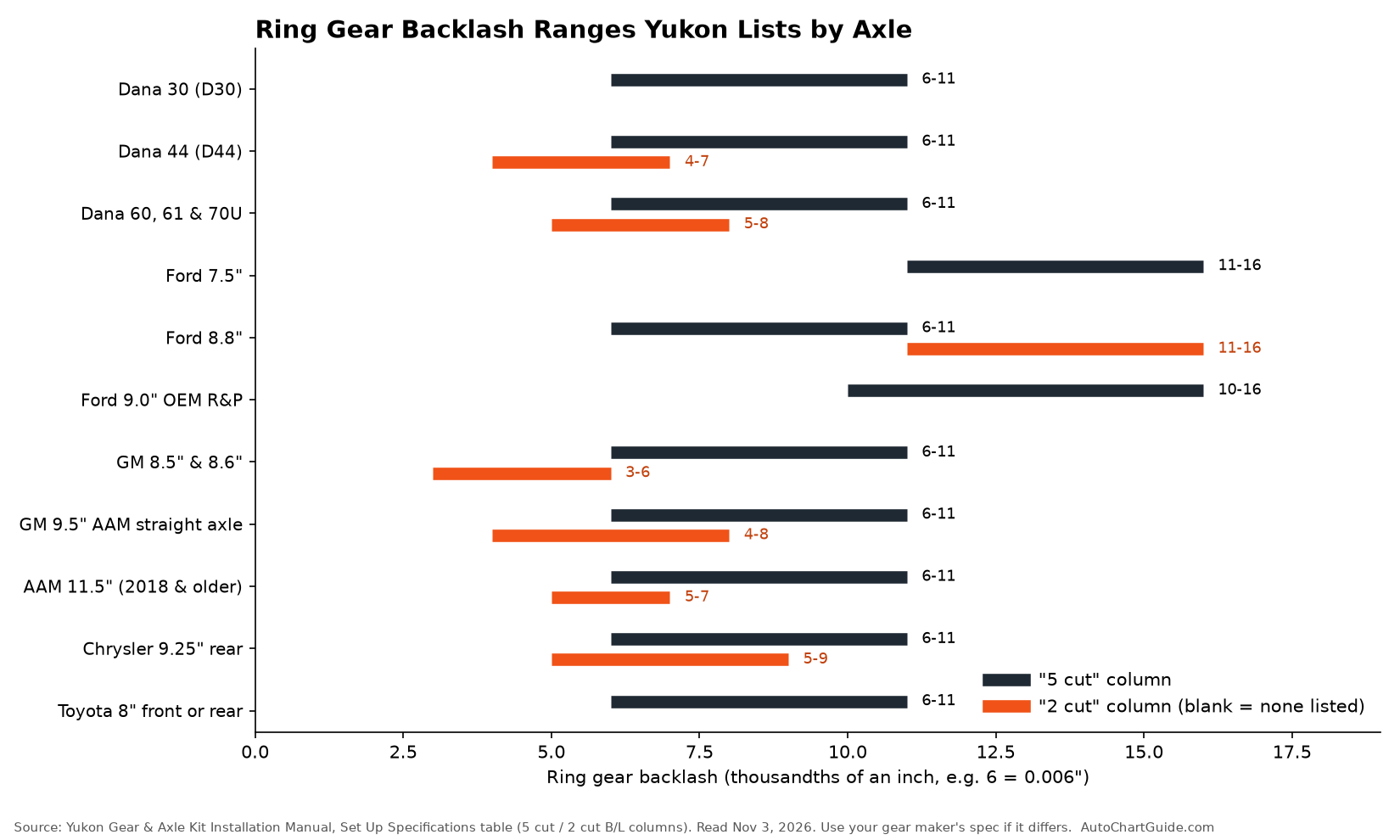
Note how the columns differ by axle. Most "5 cut" ranges in Yukon's table are .006 to .011 inch, but the Ford 7.5" and the Ford 9" OEM gear set run higher. For the Ford 8.8", Yukon's "2 cut" column is .011 to .016 inch while its "5 cut" column is .006 to .011, and Ford Performance's own sheet says .008 to .012 for its street sets. These are different gear sets from different makers, so use the number printed for the gear set you bought.
Converting a backlash change into a shim change
On shim-adjusted carriers, moving shims from one side to the other changes backlash, but not one-for-one. Ford gives the rule: change the backlash shims "in the range of 1-1/2 times the amount of backlash required." Its example: to change backlash by .004 inch, change the shim pack by .006 inch "as a starting point." Ford's 8.8 sheet prints the full table:
| Backlash change required (inch) | Differential bearing shim change (inch) |
|---|---|
| .001 | .002 |
| .002 | .002 |
| .003 | .004 |
| .004 | .006 |
| .005 | .006 |
| .006 | .008 |
| .007 | .010 |
| .008 | .010 |
| .009 | .012 |
| .010 | .014 |
| .011 | .014 |
| .012 | .016 |
| .013 | .018 |
| .014 | .018 |
| .015 | .020 |
Source: Ford Performance M-4209-8.8 instruction sheet (IS-1850-0239), backlash table on page 19, inch columns. Ford increases one differential bearing shim and decreases the other by the same amount.
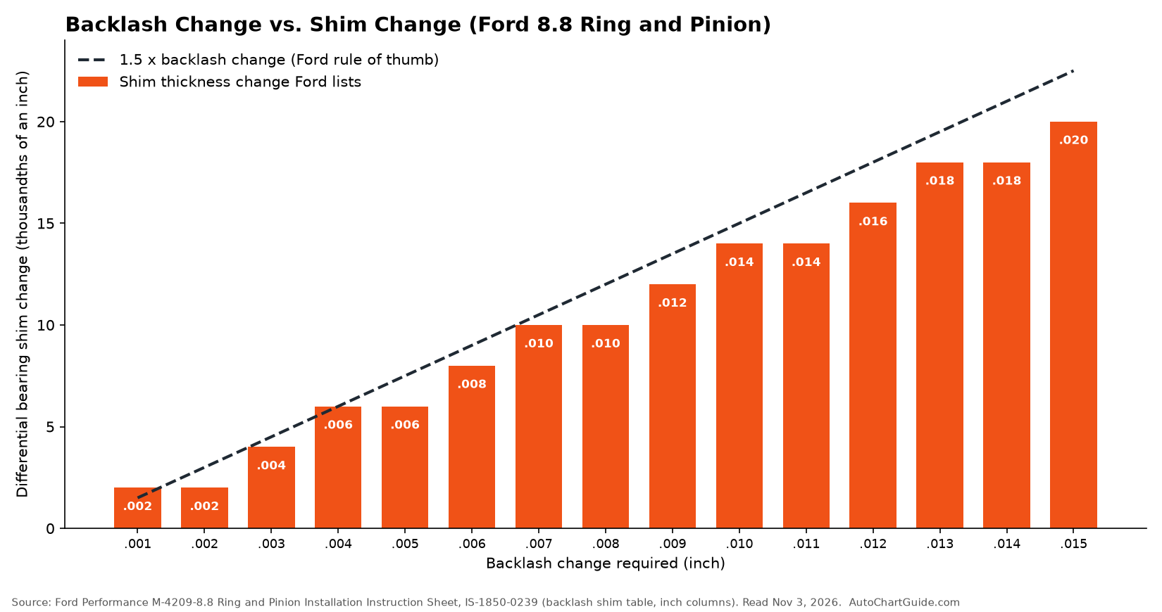
Yukon's rule of thumb is close to Ford's: "the backlash setting changes about 0.007" for each 0.010" that the carrier moves." Moving the carrier .010 inch toward the pinion removes about .007 inch of backlash, and Yukon notes that "not all ring-and-pinion sets will react exactly this way." On screw-adjuster carriers, Dana's S132 manual says each adjuster notch "equals about .003" [.08 mm] of backlash." Ford's table lists 0.335 mm beside .014 inch in its millimeter column; the inch values are the ones we charted.
How big a pinion shim change to make
Here the sources differ on step size. Ford's 8.8 sheet says pinion shims "should be changed in the range of 0.05 mm (0.002 inch) to 0.10 mm (0.004 inch) until correct pattern has been obtained." Ford's G430M sheet says pinion shims "usually must be moved in .003" increments to notice a pattern change." Yukon prefers to bracket the answer: "Consider 0.005" to 0.015" a large change and 0.002" to 0.004" a small change. Intentionally make adjustments that move the pinion too far at first." If the pattern jumps from one extreme to the other, the right depth is somewhere between, and you finish with small steps.
Worked examples: reading three common patterns
These examples apply the published tables to typical patterns. They are not measurements from a real axle.
Example 1: high on the tooth, drive toward the heel, coast toward the toe (face milled gear). Both patterns sit near the top land. Spicer's face milling chart matches "Top heel contact" on the drive side with "Top toe contact" on the coast side to "Backlash correct. Thicker pinion position shim required." Ford's movement table agrees: a thinner shim is what produces "face contact and toward the heel" on drive and "top of the tooth and slightly toward the toe" on coast, so you reverse it. Move the pinion toward the ring gear centerline, reset backlash, and roll a new pattern.
Example 2: low on the tooth and crowding the toe on both sides (face milled gear). Spicer's "Root toe contact / Root toe contact" row says "Pinion position shim correct. Increase backlash." Say your gear maker's spec is .008 to .012 inch and you read .005. To reach about .009 you need .004 inch more backlash. Ford's table gives a .006 inch shim change for a .004 inch backlash change. Move the ring gear away from the pinion with a .006 inch shim change (Ford increases one side's shim and decreases the other by the same amount), then re-measure backlash before you trust the next pattern.
Example 3: centered face to flank, but sitting toward the heel. If backlash is already in spec, this may be as good as the housing allows. Yukon's manual says the pattern's face-to-flank position "notes the pinion depth" and to "disregard the pattern's position to the tooth's heel... or toe" when setting depth, because "the housing itself influences the heel-to-toe pattern and the pattern cannot be changed without machine work." Dana's rule (heel means decrease backlash) still applies if you have room inside the backlash range.
Setting up a used ring and pinion
A gear set that has already run does not show a new-gear pattern, and you should not try to force one. Dana's S132 manual says used gearing "will not usually display the square, even contact pattern found in new gear sets" and "will normally have a 'pocket' at the heal end of the gear tooth." Its instruction is to adjust used sets "to display the same contact pattern observed before disassembly," and it counts the pattern as acceptable "as long as it does not run off the tooth at any point." It also says to check the tooth contact pattern and backlash before taking the carrier apart, so record both first.
Yukon adds a practical rule for used sets: "concentrate only on the pattern created on the coast side of the ring gear teeth. Pay little attention to the drive side."
Common ring and pinion pattern mistakes
- Using the wrong chart. Face milled and face hobbed gears have different pinion-shim rows. Check tooth depth at heel and toe before you read anything.
- Reading the pattern before backlash is in range. Yukon calls its initial backlash setting "the basis for all future adjustments." Ford and Spicer say a pinion shim change may require resetting backlash before the pattern check.
- Chasing a perfect heel-to-toe pattern. Yukon warns that trying to center it exactly "usually leads to frustration and a noisy gear set, if the face to flank pattern is not correct."
- Mixing gear sets. Ford says lapped sets "should never be mixed." Yukon says "All ring and pinion sets are matched pairs."
- Reusing a crushed sleeve. Yukon says tightening the pinion nut past the target preload "effectively destroys the crush sleeve," and the only fix is a new sleeve.
- Driving on a bad pattern. Ford's 8.8 sheet: "Do not drive vehicle if pattern is not correct."
Break-in after a new gear set
Setup is not the last step. Yukon says all new gear sets need a break-in period "to prevent overheating damage," and lists these steps: drive lightly for the first 15 to 20 miles, then stop and let the differential cool; avoid heavy acceleration for the first 100 miles; drive at least 500 miles before towing to keep the warranty; for the first tow, drive less than 15 miles with the full load, let it cool for about 20 minutes, and repeat two more times (45 miles total); and change the oil after the first 500 miles to remove metal particles and coating shed during break-in. Fill with the lubricant your axle or gear maker specifies. Our GL-4 vs GL-5 gear oil guide explains why hypoid final drives usually call for GL-5, and that limited-slip units may need a friction modifier.
If your vehicle's factory service manual covers the axle, use it alongside the gear maker's sheet. Our breakdown of the owner's manual vs. the factory service manual explains why setup specs like these are in the service manual and not the glovebox book.
FAQ
What does a good ring and pinion pattern look like?
Ford's 8.8 instruction sheet and Spicer Bulletin 5717-A describe the desirable pattern the same way: the drive pattern centered on the tooth, the coast pattern centered but possibly slightly toward the toe, and some clearance between the pattern and the top of the tooth. Ford adds that there should be no hard lines where the pressure is high.
Which side of the ring gear tooth is the drive side?
The drive side is the convex side of the ring gear tooth and the coast side is the concave side. The drive side carries load when the engine pulls the vehicle forward; the coast side carries it on deceleration.
What does it mean if the pattern is near the top of the tooth?
A pattern toward the face (top land) means the pinion is too far from the ring gear. Yukon's manual says to move the pinion toward the ring gear centerline. On axles with the pinion shim under the pinion head, Ford's and Spicer's charts describe that as a thicker pinion position shim.
What does it mean if the pattern is near the root of the tooth?
A pattern toward the flank (root) means the pinion is too close to the ring gear. Move the pinion away from the ring gear centerline, which Ford and Spicer describe as a thinner pinion position shim when the shim sits under the pinion head.
Does heel or toe contact mean the backlash is wrong?
Often. Dana's S132 manual says a pattern too close to the toe calls for more backlash (ring gear away from the pinion) and a pattern concentrated at the heel calls for less backlash. Yukon cautions that the housing also affects heel-to-toe position, so set pinion depth by the face-to-flank position and keep backlash inside the spec.
How do I tell a face hobbed gear from a face milled gear?
Compare tooth depth at the heel and the toe. Spicer Bulletin 5717-A says face hobbed teeth have equal depth at its two measuring points, while on face milled teeth one is larger. Revolution Gear puts it in heel and toe terms: a face milled (five-cut) heel is taller than the toe, and a face hobbed (two-cut) gear has constant depth from heel to toe.
How much should I change the pinion shim?
Yukon calls 0.005 to 0.015 inch a large change and 0.002 to 0.004 inch a small change, and suggests large changes until the pattern is close. Ford's 8.8 sheet says to change pinion shims in the range of 0.002 to 0.004 inch until the pattern is correct.
Should a used gear set be set up to a new-gear pattern?
No. Dana says used gearing usually shows a pocket at the heel end of the tooth, and it should be adjusted to show the same contact pattern observed before disassembly. Yukon says to concentrate mainly on the coast side pattern for most used gear sets.
Sources
- Spicer Technology, Inc. (Dana), Bulletin 5717-A, "Ring Gear and Pinion Tooth Pattern Interpretation," 5/02 (PDF hosted by a Dana parts distributor): PDF. Read November 3, 2026.
- Dana, Spicer S132 Series service manual AXSM-0059 (2018): Dana literature library PDF. Read November 3, 2026.
- Dana, Spicer Single Drive Axles service manual AXSM-8941 (2007), "Adjust Tooth Contact Pattern" section. Read November 3, 2026 (copy hosted by a third party; cited as text).
- Ford Performance, M-4209-8.8 "8.8 Ring and Pinion Installation" instruction sheet, IS-1850-0239: PDF. Read November 3, 2026.
- Ford Performance, M-4209-G430M "Ring and Pinion Set Installation Instructions," IS-1850-0276: PDF. Read November 3, 2026.
- Yukon Gear & Axle, Ring & Pinion Gear Kit Installation Instructions with Set Up Specifications (PDF dated August 2026), linked from the Yukon install manuals page: PDF. Read November 3, 2026.
- Revolution Gear & Axle, "2-Cut vs. 5-Cut Gears & Face Milling & Face Hobbing": article. Read November 3, 2026.
- Weber State University Transmission Lab, "Ring Gear Contact Pattern Interpretation of Face Hobbed (uniform tooth depth) Gear Teeth," 2011: PDF. Read November 3, 2026.