Briggs & Stratton Valve Clearance Chart 2026: Official Specs
Intake and exhaust valve clearances for Briggs & Stratton L-head, OHV and Vanguard engines, taken from Briggs's own charts and repair manuals.

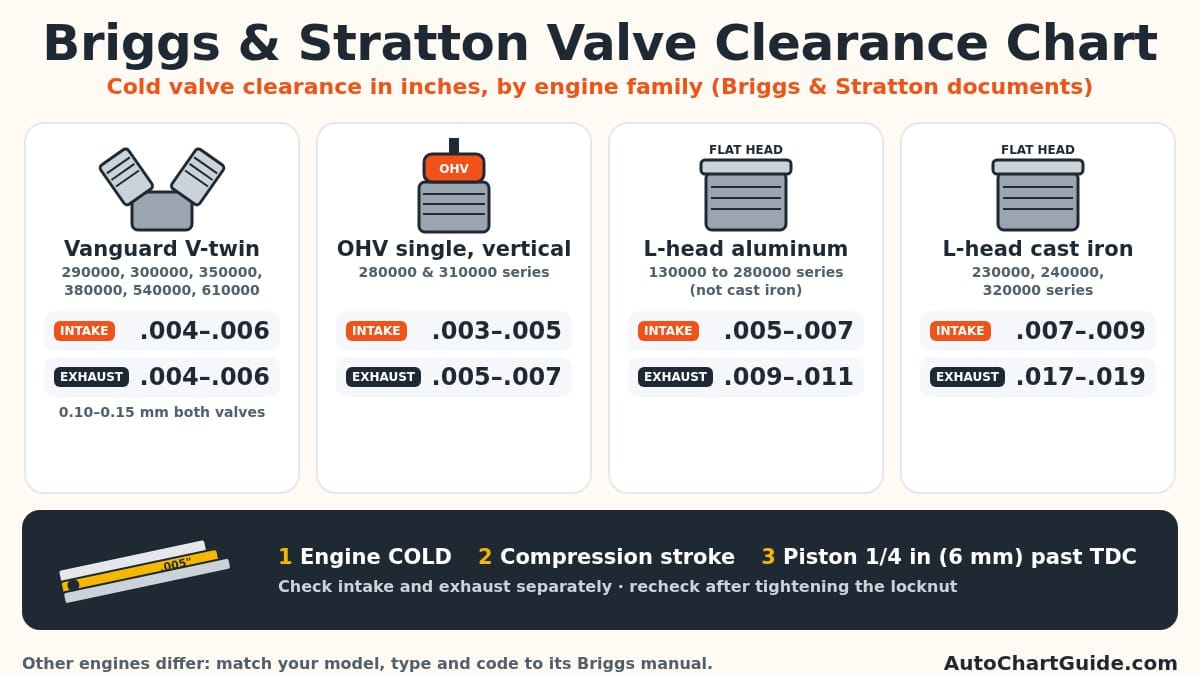
Short answer: there is no single Briggs & Stratton valve clearance. Briggs's own check chart lists ranges from .002 – .004 in on some small overhead-valve (OHV) singles up to .017 – .019 in on the exhaust valve of cast iron flathead engines. Examples: Vanguard V-twins use 0.004 – 0.006 in (0.10 – 0.15 mm) on both valves; vertical-shaft 280000 and 310000 OHV singles use .003 – .005 in intake and .005 – .007 in exhaust; aluminum L-head engines in the 130000 to 280000 series use .005 – .007 in intake and .009 – .011 in exhaust. Always check cold, with the piston 1/4 in (6 mm) past top dead center on the compression stroke.
Every figure below comes from Briggs & Stratton documents: the MS-3992 check chart (2004), repair manual 276781 (2009 edition), the 130G00 repair manual, Vanguard V-twin repair manual 272144, Briggs's valve maintenance guide (updated March 23, 2026) and its standby generator technician page. We read them all on November 1, 2026. Where two Briggs documents disagree, we print both and say so rather than picking one quietly.
Briggs & Stratton valve clearance chart by engine family
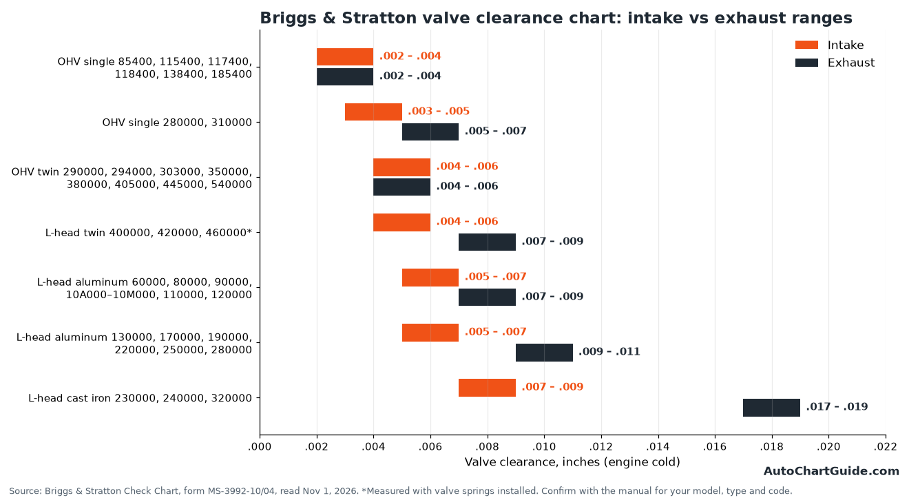
This is the widest-ranging Briggs table we found. The MS-3992 "Check Chart" groups engines by valve layout (flathead L-head or overhead valve) and by model series, the six-digit family number such as 190000 or 350000. Look up your model number first (see how to tell which row is yours), then read across.
| Engine family (Briggs model series) | Valve layout | Intake (in) | Exhaust (in) |
|---|---|---|---|
| 60000, 80000, 90000, 10A000 thru 10M000, 110000, 120000 | L-head (flathead), aluminum / cast sleeve | .005 – .007 | .007 – .009 |
| 130000, 170000, 171700, 190000, 191700, 220000, 250000, 280000 | L-head, aluminum / cast sleeve | .005 – .007 | .009 – .011 |
| 230000, 240000, 320000 | L-head, cast iron | .007 – .009 | .017 – .019 |
| 400000, 420000, 460000 (opposed twin) | L-head twin | .004 – .006* | .007 – .009* |
| 50000 | OHV single | .004 – .008 | .004 – .008 |
| 85400, 115400, 117400, 118400, 138400, 185400 | OHV single | .002 – .004 | .002 – .004 |
| 97700, 99700 | OHV single | .005 – .007 | .005 – .007 |
| 120000 horizontal shaft | OHV single | .004 – .006 | .004 – .006 |
| 120000 vertical shaft | OHV single | .004 – .008 | .004 – .008 |
| 200000, 210000 (horizontal and vertical) | OHV single | .004 – .006 | .004 – .006 |
| 235400, 245400 | OHV single | .004 – .006 | .004 – .006 |
| 280000, 310000 | OHV single | .003 – .005 | .005 – .007 |
| 290000, 294000, 303000, 350000, 380000, 405000, 445000, 540000 | OHV twin | .004 – .006 | .004 – .006 |
Source: Briggs & Stratton Check Chart, form MS-3992-10/04 (2004), valve clearance columns, read November 1, 2026. Inches only, as printed; Briggs does not give millimeters on this chart. *Briggs notes: "Clearance With Valve Springs Installed." Check every row against the manual for your exact model, type and code.
Two patterns stand out. On flathead engines the exhaust valve always gets a bigger gap than the intake, and the cast iron engines need roughly twice the exhaust clearance of the aluminum ones. On most OHV engines in this chart, the intake and exhaust figures are the same. The exceptions are the 280000 and 310000 OHV singles, where both ends of the exhaust range are .002 in larger than the intake.
Note that the same model series number can appear twice. Briggs used 120000 and 280000 for both an L-head and an OHV design, and the two need very different settings: the 280000 L-head lists .009 – .011 in on the exhaust, while the 280000 OHV lists .005 – .007 in. If you only know the series number, check whether your engine has a rocker cover on top of the cylinder head before you pick a row.
OHV single-cylinder engines: the 2009 repair manual values
Briggs repair manual 276781 covers single-cylinder OHV engines in twelve model series, and its Section 12 gives each series its own specification page. These values are printed in both inches and millimeters, and each page also lists the torque for the rocker ball set screw or nut, the fastener that locks your adjustment.
| Model series (2009 manual) | Intake | Exhaust | Rocker ball set screw or nut |
|---|---|---|---|
| 110000 horizontal | .004 – .006 in (.10 – .15 mm) | .009 – .011 in (.23 – .28 mm) | 45 lb-in (5 Nm) |
| 120000 horizontal | .004 – .006 in (.10 – .15 mm) | .009 – .011 in (.23 – .28 mm) | 45 lb-in (5 Nm) |
| 150000 horizontal | .004 – .006 in (.10 – .15 mm) | .009 – .011 in (.23 – .28 mm) | 45 lb-in (5 Nm) |
| 200000 horizontal | .004 – .006 in (.10 – .15 mm) | .004 – .006 in (.10 – .15 mm) | 45 lb-in (5 Nm) |
| 210000 horizontal | .004 – .006 in (.10 – .15 mm) | .004 – .006 in (.10 – .15 mm) | 45 lb-in (5 Nm) |
| 97700 & 99700 vertical | .005 – .007 in (.13 – .18 mm) | .005 – .007 in (.13 – .18 mm) | 45 lb-in (5 Nm) |
| 110000 vertical | .003 – .005 in (.08 – .13 mm) | .005 – .007 in (.13 – .18 mm) | 45 lb-in (5 Nm) |
| 120000 vertical | .003 – .005 in (.08 – .13 mm) | .005 – .007 in (.13 – .18 mm) | 45 lb-in (5 Nm) |
| 210000 vertical | .003 – .005 in (.08 – .13 mm) | .005 – .007 in (.13 – .18 mm) | 45 lb-in (5 Nm) |
| 280000 vertical | .003 – .005 in (.08 – .13 mm) | .005 – .007 in (.13 – .18 mm) | 45 lb-in (5 Nm) |
| 310000 vertical | .003 – .005 in (.08 – .13 mm) | .005 – .007 in (.13 – .18 mm) | 45 lb-in (5 Nm) |
| 330000 vertical | .003 – .005 in (.08 – .13 mm) | .003 – .005 in (.08 – .13 mm) | 45 lb-in (5 Nm) |
Source: Briggs & Stratton Repair Manual 276781 (Part No. 276781-8/09), Single Cylinder OHV, Section 12 Engine Specifications, read November 1, 2026. Millimeters as printed by Briggs.
The horizontal-shaft 110000, 120000 and 150000 engines are the outliers here. Their exhaust valve gets .009 – .011 in, more than double the .004 – .006 in on the intake, so setting both valves to the same feeler blade would leave the exhaust far too tight. Most of the vertical-shaft engines share one pattern: .003 – .005 in intake and .005 – .007 in exhaust. The 330000 vertical is different again, with .003 – .005 in on both valves.
Where the 2004 chart and the 2009 manual disagree
Comparing the two Briggs documents line by line shows that three model series have different figures. We cannot tell from the documents themselves whether Briggs changed the specification for later production or corrected an error, because neither one explains it.
| Model series | MS-3992 check chart (2004) | Repair manual 276781 (2009) | Agree? |
|---|---|---|---|
| 120000 horizontal OHV | Intake .004 – .006, exhaust .004 – .006 | Intake .004 – .006, exhaust .009 – .011 | No, exhaust differs |
| 120000 vertical OHV | Intake .004 – .008, exhaust .004 – .008 | Intake .003 – .005, exhaust .005 – .007 | No |
| 210000 vertical OHV | Intake .004 – .006, exhaust .004 – .006 | Intake .003 – .005, exhaust .005 – .007 | No |
| 200000 / 210000 horizontal OHV | .004 – .006 both | .004 – .006 both | Yes |
| 97700, 99700 vertical OHV | .005 – .007 both | .005 – .007 both | Yes |
| 280000, 310000 vertical OHV | Intake .003 – .005, exhaust .005 – .007 | Intake .003 – .005, exhaust .005 – .007 | Yes |
All values in inches, compared on November 1, 2026. Neither document says it replaces the other.
The practical rule is the one Briggs itself gives in its valve maintenance guide: newer engine models include valve clearances in the operator's manual, and for older engines you should use the repair manual. If your exact model is covered by a manual you can download for that model, use that manual. If the only sources you have conflict, a Briggs & Stratton dealer can look up the model, type and code. The same problem shows up with car data, which we cover in why car specs differ between websites; the answer is the same, too: trust the document written for your exact unit.
Newer single-cylinder OHV engines (130G00 family)
Briggs's 130G00 repair manual covers a group of single-cylinder OHV engines with model numbers that use letters in the design position, such as 130G00 and 13U100. It gives separate intake and exhaust figures for two sub-groups.
| Engine models | Intake | Exhaust | Rocker ball locknut torque |
|---|---|---|---|
| 130G00, 131G00, 13R200 | 0.004 – 0.006 in (0.10 – 0.15 mm) | 0.006 – 0.008 in (0.15 – 0.20 mm) | 60 – 80 lb-in (6.8 – 9 N-m) |
| 13U100, 13U200 | 0.005 – 0.007 in (0.13 – 0.18 mm) | 0.005 – 0.007 in (0.13 – 0.18 mm) | 71 – 124 lb-in (8 – 14 N-m) |
Source: Briggs & Stratton 130G00 Repair Manual, printed pages 18 – 19, read November 1, 2026.
These are good examples of why you should not reuse settings from a "similar" engine. The 130G00 and 13U100 are both 13-series engines from the same manual, yet one sets the exhaust at 0.006 – 0.008 in and the other at 0.005 – 0.007 in, and their lock nut torques are different as well.
Vanguard V-twin and standby generator engines
For the Vanguard V-twins in repair manual 272144, every model series in Section 13 lists the same cold clearance for both valves. The procedure in Section 1 gives a single target, 0.005 in (0.13 mm), the middle of that range.
| Engine | Intake | Exhaust | Adjuster lock nut torque | Source |
|---|---|---|---|---|
| Vanguard V-twin 290000, 300000 | 0.004 – 0.006 in (0.10 – 0.15 mm) | 0.004 – 0.006 in (0.10 – 0.15 mm) | 70 lb-in (8 Nm) | Repair manual 272144, Section 13 |
| Vanguard V-twin 350000 | 0.004 – 0.006 in (0.10 – 0.15 mm) | 0.004 – 0.006 in (0.10 – 0.15 mm) | 70 lb-in (8 Nm) | Repair manual 272144, Section 13 |
| Vanguard V-twin 380000 | 0.004 – 0.006 in (0.10 – 0.15 mm) | 0.004 – 0.006 in (0.10 – 0.15 mm) | 70 lb-in (8 Nm) | Repair manual 272144, Section 13 |
| Vanguard V-twin 540000, 610000 | 0.004 – 0.006 in (0.10 – 0.15 mm) | 0.004 – 0.006 in (0.10 – 0.15 mm) | 70 lb-in (8 Nm) | Repair manual 272144, Sections 1 and 13 |
| Two-cylinder engines in Briggs home standby generators | 0.004 – 0.006 in (0.102 – 0.152 mm) | 0.007 – 0.009 in (0.178 – 0.229 mm) | 70 in-lb (8 Nm) | Briggs Energy Solutions technician troubleshooting page |
All clearances measured cold. Read November 1, 2026. For the Vanguard rows, 70 lb-in is the "Rocker Arm Lock Nut" torque in each Section 13 torque list.
The standby generator figures are a useful warning. Those two-cylinder engines also use 0.004 – 0.006 in on the intake, but Briggs Energy Solutions lists 0.007 – 0.009 in on the exhaust. If you assume "Briggs twin = .004 – .006 on both valves" on a generator, the exhaust valves end up too tight.
How to tell which row is yours
Briggs identifies every engine by three numbers stamped into it: model, type and code. On lawn mower engines, Briggs says the model number is usually stamped into the blower housing, the muffler heat shield or a few inches above the spark plug, and also on the fuel tank and base of the block. You may need to remove a shroud to see it. On many horizontal-shaft OHV engines the numbers are stamped into the rocker cover, and some generator makers fit a decorative chrome cover over it.
Do not use the numbers on the emissions label. Briggs warns that they can be confused with the model, type and code but cannot be used to identify the engine.
Once you have the model number, Briggs's numbering chart tells you how to read it:
| Position in model number | What it tells you | Example: 303447 |
|---|---|---|
| First one or two digits | Approximate cubic inch displacement | 30 = 30 cubic inches |
| Next digit | Basic design series | 3 = design series 3 |
| Next digit | Crankshaft orientation: 0 – 4 and A – G horizontal, 5 – 9 and H – Z vertical | 4 = horizontal shaft |
| Next digit | Bearings, lubrication, reduction gear or auxiliary drive | 4 = ball bearing, flange mounting, pressure lubrication |
| Last digit | Type of starter | 7 = electric starter, 12 or 24 volt gear drive with alternator |
Source: Briggs & Stratton, "Your Key to the World's Finest Engines" numbering chart (revised 2/06), read November 1, 2026.
The first digits give you the model series used in the charts above. A model beginning with 28 belongs to the 280000 series, and one beginning with 31 to the 310000 series. The orientation digit tells you whether to use a "horizontal" or "vertical" row, which matters for the 120000 and 210000 OHV engines. Then decide whether the engine is an L-head or an OHV design. An OHV engine has a valve cover (rocker cover) bolted to the top of the cylinder head, and the L-head charts do not apply to it.
When the model number uses letters in the design position (for example 13U100), find that model's own repair or operator's manual on the Briggs & Stratton manuals page. Do not assume the six-digit series charts cover it. If you are not sure what each kind of manual contains, our guide to owner's manuals versus service manuals explains the difference.
How to check and adjust OHV valve clearance
This is the procedure from Briggs repair manual 276781 and the 130G00 manual, combined with Briggs's maintenance guide. Use the clearance and torque figures for your exact engine.
- Start with a cold engine. Both repair manuals tell you to check clearance cold, and the Vanguard specifications are headed "Valve Clearance – Measured Cold."
- Disconnect the spark plug wire and remove the plug. Clean around the plug first so dirt does not fall into the cylinder. While the plug is out, check its gap against our Briggs and Stratton spark plug chart.
- Remove the valve (rocker) cover. The 130G00 manual uses four hex flange screws; your engine may differ.
- Find top dead center on the compression stroke. Turn the crankshaft by hand in the direction of engine rotation and watch the rocker arms. The 130G00 manual says that after the exhaust valve closes, the intake begins to open; when the intake closes, both valves are closed and the rocker arms are loose. Manual 276781 explains why this matters: starting from the compression stroke "prevents the compression release from holding the valves open."
- Move the piston 1/4 in (6 mm) past top dead center. Put a wooden dowel or narrow rod through the spark plug hole and onto the piston. Turn until the dowel reaches its highest point, mark it level with the top of the plug hole, make a second mark 1/4 in above the first, and keep turning until the second mark is level with the hole.
- Measure each valve with a feeler gauge between the rocker arm and the valve stem. Check intake and exhaust separately; many engines use different figures for each.
- Adjust if needed. Loosen the locknut and turn the rocker ball nut or adjusting screw until the feeler blade for your target clearance just fits between rocker and stem. Hold the adjuster still and tighten the locknut or set screw to the specified torque.
- Measure again. Both manuals tell you to recheck after tightening, because the adjuster can move as you tighten it.
- Refit the cover with a clean gasket surface. The 130G00 manual says to remove old gasket material, fit a new gasket and tighten the screws in a crosswise pattern.
- Repeat for each cylinder on twins. Briggs says the 1/4 in past top dead center procedure must be done for each cylinder on V-twin and opposed-twin engines.
The lock nut torques are small, in pound-inches rather than pound-feet, so use a torque wrench that reads in lb-in. If yours reads in other units, our guide on how to read a torque wrench covers the scales.
Choosing a feeler blade for a range
Most Briggs figures are ranges, such as .004 – .006 in. Any clearance inside it meets the specification. A simple way to check is to try the blades at each end: the thinner one (.004) should slide in and the thicker one (.006) should not. To set a valve, aim for the middle of the range, which is exactly what the Vanguard manual does when it gives 0.005 in as the single target for a 0.004 – 0.006 in range. On a range like .003 – .005 in, that middle blade is .004 in.
Some feeler gauges are marked in millimeters only. Briggs prints millimeter values in manuals 276781, 130G00 and 272144, so use those printed values rather than converting the inch figures yourself. The MS-3992 chart is inches only.
L-head (flathead) engines: setting clearance without an adjuster
Side-valve engines, such as the 60000 to 320000 L-head families in the first table, work differently. The valves sit beside the cylinder rather than in the head, and Briggs's L-head procedure has no adjusting-screw step. Briggs's valve guide explains that lapping the valves removes a small amount of material from the valve face and seat, so you may need to reset the tappet clearance after a valve job.
Briggs's method for L-head engines: turn the crankshaft to top dead center with both valves closed, then turn past it until the piston is 1/4 in down from the top of the cylinder, and check the gap between each valve stem and its tappet with a feeler gauge. If the clearance is too small, Briggs says to remove the valve and grind or file the end of the stem square to increase it, checking often "as it is easy to remove too much metal." Filing can only increase clearance, so it cannot correct a gap that is already too large.
The MS-3992 chart flags one more detail for the 400000, 420000 and 460000 opposed twins: their figures are "Clearance With Valve Springs Installed." Measure those engines with the springs in place.
Why valve clearance matters
Valve clearance is the small gap between the valve stem and the rocker arm or tappet when the valve is closed, and Briggs specifies it with the engine cold. A gap that is too small can stop a valve from seating fully. Briggs's Vanguard repair manual lists "insufficient valve clearance" among the causes to look for when a cylinder shows poor compression, alongside burned valves, a blown head gasket and worn rings.
Briggs also links valve clearance to starting. Its standby generator troubleshooting page lists "Engine Valve Adjustment needed" as a potential cause of a Fail to Start alarm, and its OHV procedure is built around the compression release, the mechanism that holds a valve slightly open while cranking so the engine is easier to turn over. That is why you must start from the compression stroke rather than any point where the valves happen to look closed. If your engine is suddenly hard to pull or hard to start, clearance is worth checking, but it is only one possible cause. Ignition, fuel and compression checks are covered in the troubleshooting sections of the same manuals.
That generator page also puts the checks in order. When an engine fails to start, the technician checks the air filter, then spark, then crankcase vacuum, and only then valve clearance. That is a sensible order for any small engine.
Common mistakes to avoid
- Using one number for every Briggs engine. Within the documents above, exhaust ranges run from .002 – .004 in to .017 – .019 in.
- Setting both valves the same when they are not. In manual 276781, the 110000, 120000 and 150000 horizontal engines and most vertical singles use a different exhaust figure, and so do the standby generator twins.
- Measuring a warm engine. Every specification here is for a cold engine.
- Checking at the wrong top dead center. On the exhaust stroke, or with the compression release active, the readings will be wrong.
- Forgetting to recheck after tightening the locknut. Repair manuals 276781 and 130G00 and Briggs's standby generator procedure all include this step.
- Using an emissions label number. Briggs says it cannot identify the engine.
- Trusting a single web table. Briggs's own documents differ on some engines. Third-party tables add their own differences: one third-party web table we checked lists the 138400 OHV at .005 – .008 in, where Briggs's MS-3992 chart prints .002 – .004 in. Check the Briggs source.
A valve adjustment is often part of a bigger service. If you are changing the oil at the same time, our Briggs and Stratton oil filter chart lists the official filter numbers by engine.
Frequently asked questions
What is the valve clearance on a Briggs and Stratton engine?
It depends on the model series. Briggs's MS-3992 check chart lists ranges from .002 – .004 in on some small OHV singles up to .017 – .019 in on the exhaust valve of cast iron L-head engines. Find your model number first, then read the row for that series in the manual for your engine.
Do I check Briggs valve clearance hot or cold?
Cold. Briggs's repair manuals say to check valve clearance with the engine cold, and the Vanguard V-twin specifications are labelled "Valve Clearance – Measured Cold."
Where should the piston be when I set the valves?
On the compression stroke, 1/4 inch (6 mm) past top dead center, so both valves are closed. Repair manual 276781 says starting from top dead center on the compression stroke prevents the compression release from holding the valves open.
Are intake and exhaust clearances the same on Briggs engines?
Sometimes. Vanguard V-twins in repair manual 272144 use 0.004 – 0.006 in for both valves. Many other engines use a larger exhaust gap: aluminum L-head 130000 to 280000 series engines list .009 – .011 in exhaust against .005 – .007 in intake.
How do I adjust valves on a flathead (L-head) Briggs engine?
Briggs's L-head procedure has no adjusting screw. It says that if tappet clearance is too small, you remove the valve and grind or file the end of the stem square to increase it, checking often because it is easy to remove too much.
What torque do I use on the rocker arm lock nut?
It depends on the engine. Repair manual 276781 lists 45 lb-in (5 Nm) for the rocker ball set screw or nut. The 130G00 manual lists 60 – 80 lb-in or 71 – 124 lb-in depending on the model, and Vanguard V-twins use 70 lb-in (8 Nm).
Why do two Briggs charts give different valve clearances for my engine?
Briggs has printed different figures for the same model series in different documents. The 2004 MS-3992 check chart and the 2009 repair manual 276781 disagree on 120000 and vertical 210000 OHV engines. Use the manual that covers your exact model, type and code, or ask a Briggs dealer.
Can I use the numbers on the emissions label to look up my engine?
No. Briggs warns that numbers on the engine emissions label can be confused with the model, type and code, and cannot be used to identify the engine.
Sources
- Briggs & Stratton, Check Chart: Common Specifications, form MS-3992-10/04 (PDF, 2004; hosted by retailer MyMowerParts). Read November 1, 2026.
- Briggs & Stratton, Repair Manual 276781 (Part No. 276781-8/09), Single Cylinder OHV, Section 12 Engine Specifications (online copy). Read November 1, 2026.
- Briggs & Stratton, Repair Manual 276781, "Adjust Valve Clearance" procedure (online copy). Read November 1, 2026.
- Briggs & Stratton, 130G00 Repair Manual, Check/Adjust Valve Clearance (ManualsLib copy). Read November 1, 2026.
- Briggs & Stratton, Vanguard V-Twin OHV Repair Manual 272144 (PDF hosted by Mud Buddy). Read November 1, 2026.
- Briggs & Stratton, "Small Engine Valve Maintenance & Repair," updated March 23, 2026. Read November 1, 2026.
- Briggs & Stratton Energy Solutions, "Service & Troubleshooting – Technician Support" (home standby generators). Read November 1, 2026.
- Briggs & Stratton, "How Can I Find the Engine Serial / Model Number, Type & Trim?" updated January 15, 2026. Read November 1, 2026.
- Briggs & Stratton, "Your Key to the World's Finest Engines" model numbering chart (PDF, revised 2/06). Read November 1, 2026.
- Briggs & Stratton, manuals lookup. Read November 1, 2026.